Introduction
As an engineer who has studied the CWNP track and taken the CWAP exam, I have seen enough evidence to build a strong argument for disabling MU-MIMO, especially when researching best practices for very high-density wireless deployments within large public venues.
This is only the start of the journey, as, will be explained, capturing this traffic leads into an ever-expanding rabbit hole, and life gets in the way quickly!
Before we get into it, this is pretty acronym-heavy, so to recap:
- AP – Access Point
- STA – Station (Client)
- BSS – Basic Service Set
- HE – High Efficiency (802.11ax)
- VHT – Very High Throughput (802.11ac)
- RA – Receiver Address
- TA – Transmitter Address
- SU – Single User
- MU – Multi-User
- MIMO – Multiple Input, Mulitple Output
- OFDM – Orthogonal Frequency-Division Multiplexing
- OFDMA – Orthogonal Frequency-Division Multiple Access
- UL-OFDMA – Uplink Orthogonal Frequency-Division Multiple Access
- DL-OFDMA – Downlink Orthogonal Frequency-Division Multiple Access
- TxBf – Transmit Beamforming
- CSI – Channel State Information
- NDP – Null Data Packet
- NDPA – Null Data Packet Announcement
- MU-BRP – Multi-User Beamforming Report Poll
- MU-BAR – Multi-User Block ACK Request
- HD – High Density
MU-MIMO, which was introduced in 802.11ac Wave 2 Standard (IEEE 802.11-2016), uses TxBF to enable a single AP to communicate with multiple devices at the same time, in downlink only, thus technically increasing the available capacity within a BSS.
In the 802.11ax Standard (IEEE 802.11ax-2021), which was updated to also support MU-MIMO on downlink and uplink transmissions, as well as a new method to calibrate the channel.
This sounds great on paper, and surely something that would be beneficial within a high-density network, however, there is an associated cost, that ultimately makes it inefficient, which is what we will explore in this article.
To confirm my suspicions, we must first look at how TxBF is used to calibrate the channel through a mechanism called “Sounding”.
Sounding is a process by which an access point gathers CSI to determine the optimal way to transmit data to a receiver or group of receivers, theoretically, there can be up to 62 MU-MIMO groups and the number of clients within a group can be up to 4 (802.11ac) or 8 (802.11ax), this is also highly dependant on the number of spatial streams supported by the AP.
The maximum number of STAs within an MU-MIMO group is also directly proportional to the number of spatial streams supported by the AP, hence why on enterprise-class products, promoted for use in HD deployments, it was common to see up to 8 being supported.
But first, some basic principles for effective MU-MIMO operation.
- Stations (STAs) must be spatially separated from one another.
- The AP must have data to send to all STAs within an MU-MIMO group.
- STAs and APs must both support the feedback mechanisms to calculate CSI.
- The time required to transmit data to each STA within a MU-MIMO group has to be similar.
- Best suited to high bandwidth applications.
- Performs best at short and medium ranges between AP and STA.
Channel Sounding Process – 802.11ac vs 802.11ax
The sounding process is a frame exchange between the beamformer (AP) and the beamformees (STAs) to measure the channel and calculate channel state information, ending with the creation of a steering matrix, which dictates how the beamformer should steer energy towards the beamformee.
802.11ax brought several improvements to the WiFi standard, per the moniker. High Efficiency, one of which was making the process of channel calibration more streamlined.
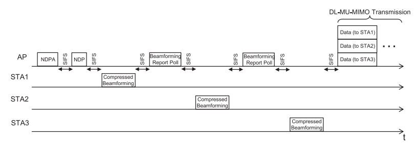
In 802.11ac Wave 2, the sounding process is as follows:
- The AP sends an NDPA control frame on a broadcast address, indicating the STAs that are required to provide CSI.
- An NDP follows the NDPA, this is a physical layer frame (PHY) containing no user data but used for channel estimation and sent on every spatial stream.
- After receiving the NDP each STA calculates the Feedback Matrix (V).
- The first STA indicated within the NDPA frame responds with a Compressed Beamforming report, containing the steering matrix.
- The AP uses another control frame (Beamforming Report Poll) sent directly to each STA within the MU-MIMO group to request transmission of their compressed beamforming reports.
- Once compressed beamforming report frames are collated from all STAs within the MU-MIMO group a Steering Matrix (Q) is computed and data is transmitted to each STA simultaneously.
- Each STA then sends a Block Acknowledgement in sequence.
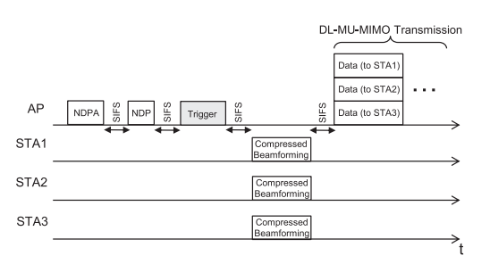
In 802.11ax, the sounding process is as follows, and can utilise either OFDM or OFDMA.
- The AP sends an NDPA control frame on a broadcast address, indicating the STAs are required to provide CSI.
- An NDP follows the NDPA, this is a physical layer frame (PHY) containing no user data but used for channel estimation and sent on every spatial stream.
- After receiving the NDP each STA calculates the Feedback Matrix (V).
- The AP sends a broadcast Beamforming Report Poll (BFRP) Trigger frame indicating all STAs within the MU-MIMO group.
- Using multiplexing, STAs respond by sending their Compressed Beamforming reports using either UL-MU-MIMO or UL-OFDMA, the latter being simultaneous.
- Once compressed beamforming report frames are collated from all STAs within the MU-MIMO group a Steering Matrix (Q) is computed and data is transmitted to each STA simultaneously.
- AP sends a Trigger Frame named MU-BAR to indicate all STAs to send Block Acknowledgements using UL-OFDMA. However, STAs may sequentially send Block Acks in the event that UL-OFDMA isn’t available.
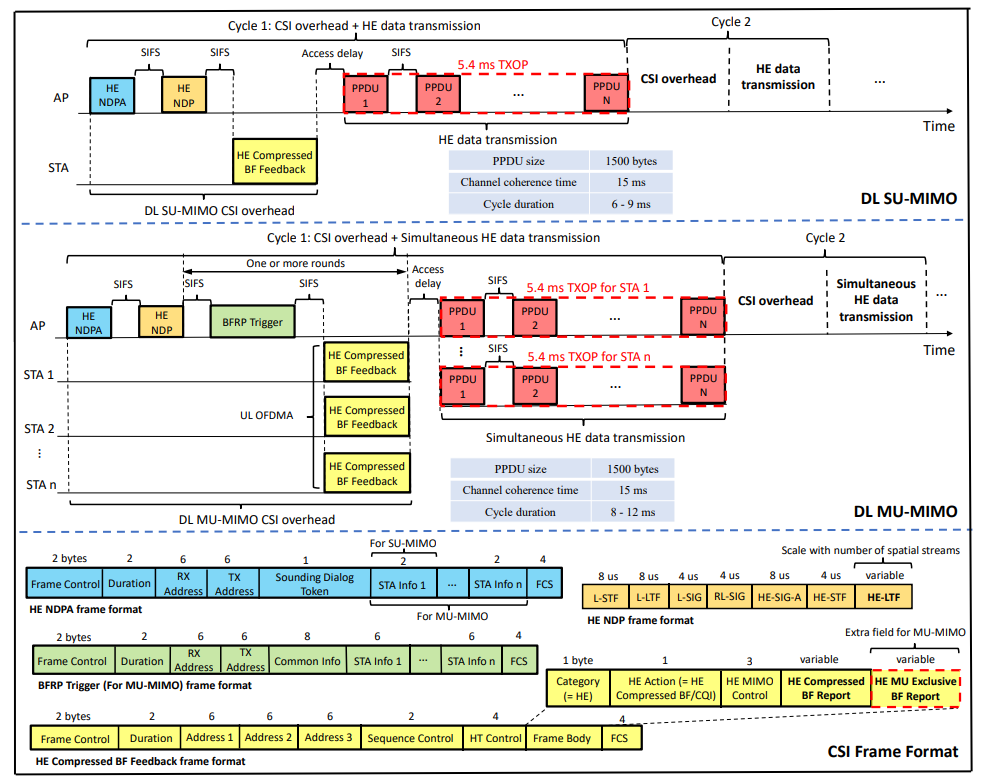
The frame format for DL SU and DL MU-MIMO full HE data transmission is shown below.
Channel Sounding – Packet Analysis
Capturing OFDMA frames can be quite a challenge, as documented by Gjermund Raaen quite successfully in this video – How to capture 802 11ax OFDMA traffic with Jetson Nano
As such, when trying to capture HE MU-MIMO frames transmitted using OFDMA is problematic at best, however, we can fill in the gaps by observing frames that we can see, such as control and trigger frames.
What I would like to evaluate is the size of the MU-MIMO frames exchanged in the sounding process and observe the frequency at which they’re sent.
Before we begin, and to make it easier on the eye I have used the Wireshark ethers file to map client MAC addresses to an alias, i find that this helps greatly when troubleshooting so identity conversations between transmitters and receivers.
Wireshark Ethers File Setup
Location: C:\Users\%Username%\AppData\Roaming\Wireshark\ff-ff-ff-ff-ff-ff BCAST
cc:15:31:fe:b6:59 LAPTOP
70:f0:96:fd:70:4b ACCESSPOINT
71:f0:96:fd:70:4b ACCESSPOINT
de:4f:f6:2d:4e:99 IPHONE16
3c:06:30:30:cf:3d MACBOOK
ea:d6:e8:73:2e:c4 IPAD-1
8e:8c:a1:cc:8d:3e IPAD-2Test Environment
- Cisco 9130AXI Wireless Access Point (EWC Mode v17.9.5)
- 8×8 uplink/downlink MU-MIMO with eight spatial streams
- 20Mhz Channel Width
- Open SSID / No Encryption
- WLANPi w/ Comfast AX1800 WiFi 6 Adapter
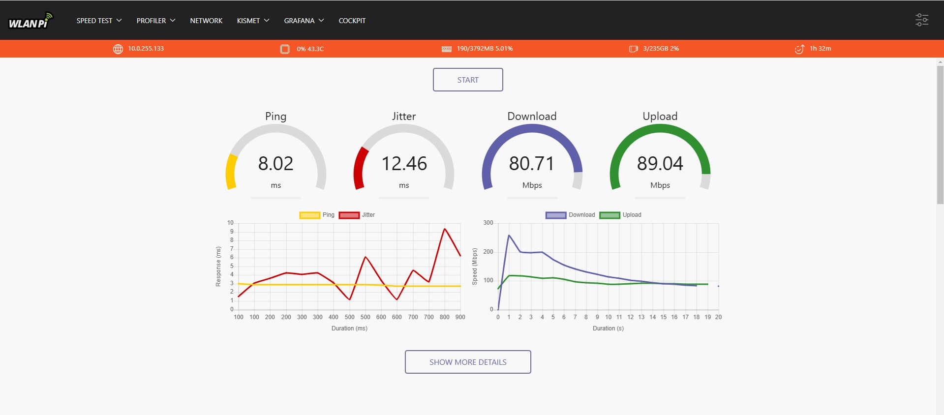
- LibreSpeed on the WLANPi used for traffic generation (Thank you WLANPi Guys!)
- WLANPi was connected to the same wired network segment as wireless user traffic @ 1Gb/s
- Windows 11 Laptop (Intel AX201 Chipset)
- Apple Macbook Pro M1 2020
- Apple iPad Pro
- Apple iPhone 16
Due to the lack of space within the test area (~8x8m) I tried to position the clients within the corner of the room and distributed them around the AP to try and improve spatial separation and provide better conditions to initiate an MU-MIMO transmission.
To try and emulate high throughput, I ran a speed test simultaneously from all STAs simataniously and captured the data using the WLANPi directly into Wireshark.
Access Point Configuration
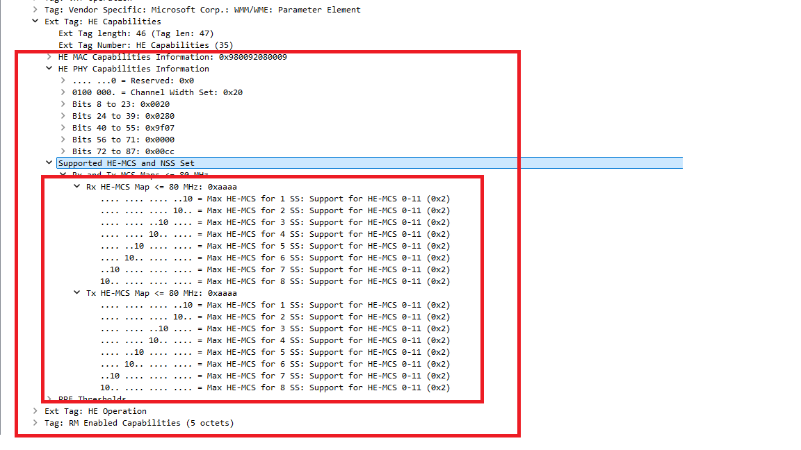
To double-check that the AP supports 8 spatial streams we can observe this within the HE Capabilities Information Element (IE)
Cisco Wireless LAN Controller Configuration
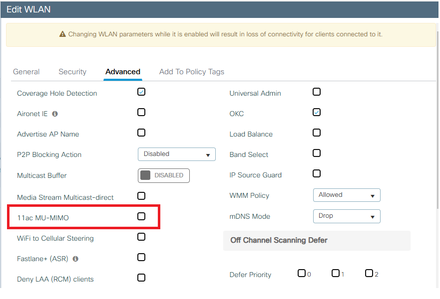
On a Cisco Wireless LAN Controller, running IOS-XE, MU-MIMO can be enabled independently, per WLAN profile.
This can be configured either via the GUI interface or via CLI.
From the GUI, navigate to Configuration > Tags & Profiles WLANs > WLAN
It is also possible to enable or disable 802.11ac MU-MIMO independently of 802.11ax.
NB: If 802.11ac MU-MIMO is enabled and 802.11ax MU-MIMO is disabled, 802.11ax capable clients will not use MU-MIMO at all. When viewing a packet capture in this configuration, no channel sounding is attempted.
From the CLI, this can be achieved using the following commands.
Device# configure terminal
Device(config)# wlan wlan1
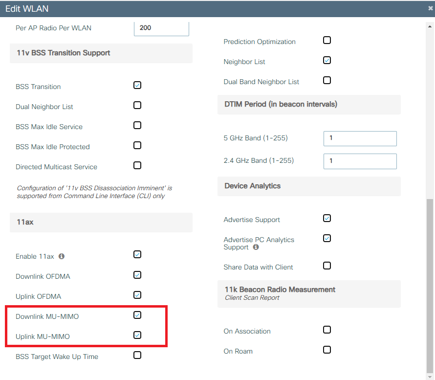
Device(config-wlan)# dot11ax downlink-mumimo
Device(config-wlan)# dot11ax uplink-mumimoThroughput Testing
To generate traffic and try to encourage STAs to use MU-MIMO I set up Librespeed on the WLANPi to run for a period of 30 seconds, unfortunately, without being able to schedule this on all clients at the same time, it involved me running around the room and starting is manually, thus the start/end of the test would be slightly offset, but still hoped the frames generated when all STAs were communicating in both DL and UL, it would trigger MU-MIMO.
For HE MU-MIMO to operate as expected, it is assumed that OFDMA also must be enabled on the WLAN profile, a byproduct of this though is that STAs may choose to use OFDMA instead of MU-MIMO for multi-user transmissions.
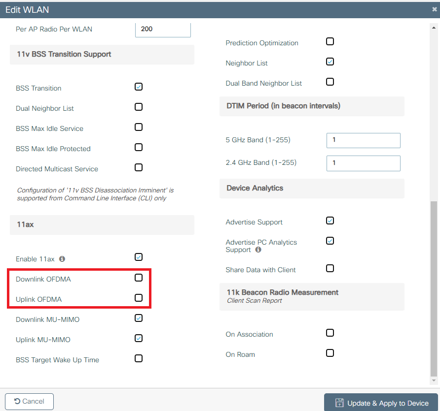
To disable OFMDA from the GUI, navigate to Configuration > Tags & Profiles WLANs > WLAN
To disable OFMDA from the CLI, this can be achieved using the following commands.
Device# configure terminal
Device(config)# wlan wlan1
Device(config-wlan)# no dot11ax downlink-ofdma
Device(config-wlan)# no dot11ax uplink-ofdma
Throughput Testing – Results
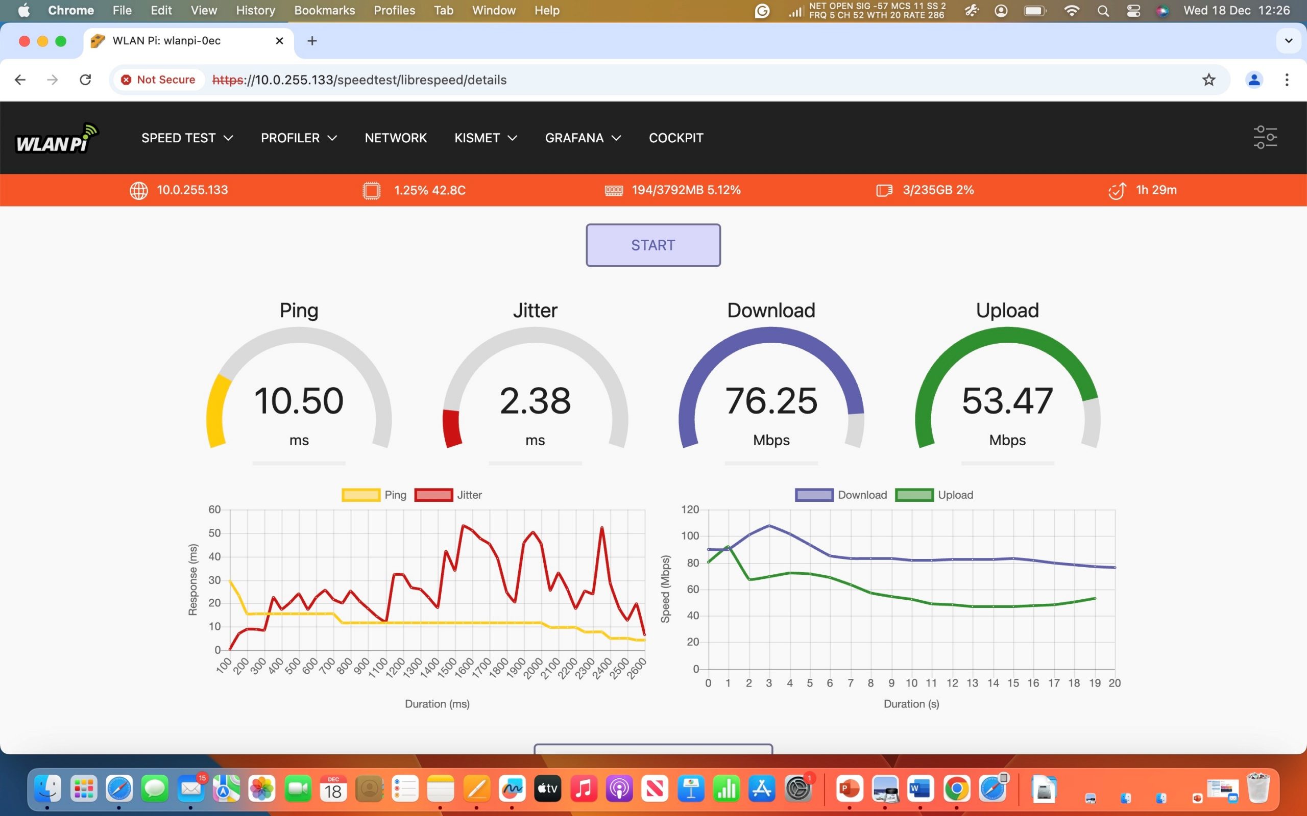
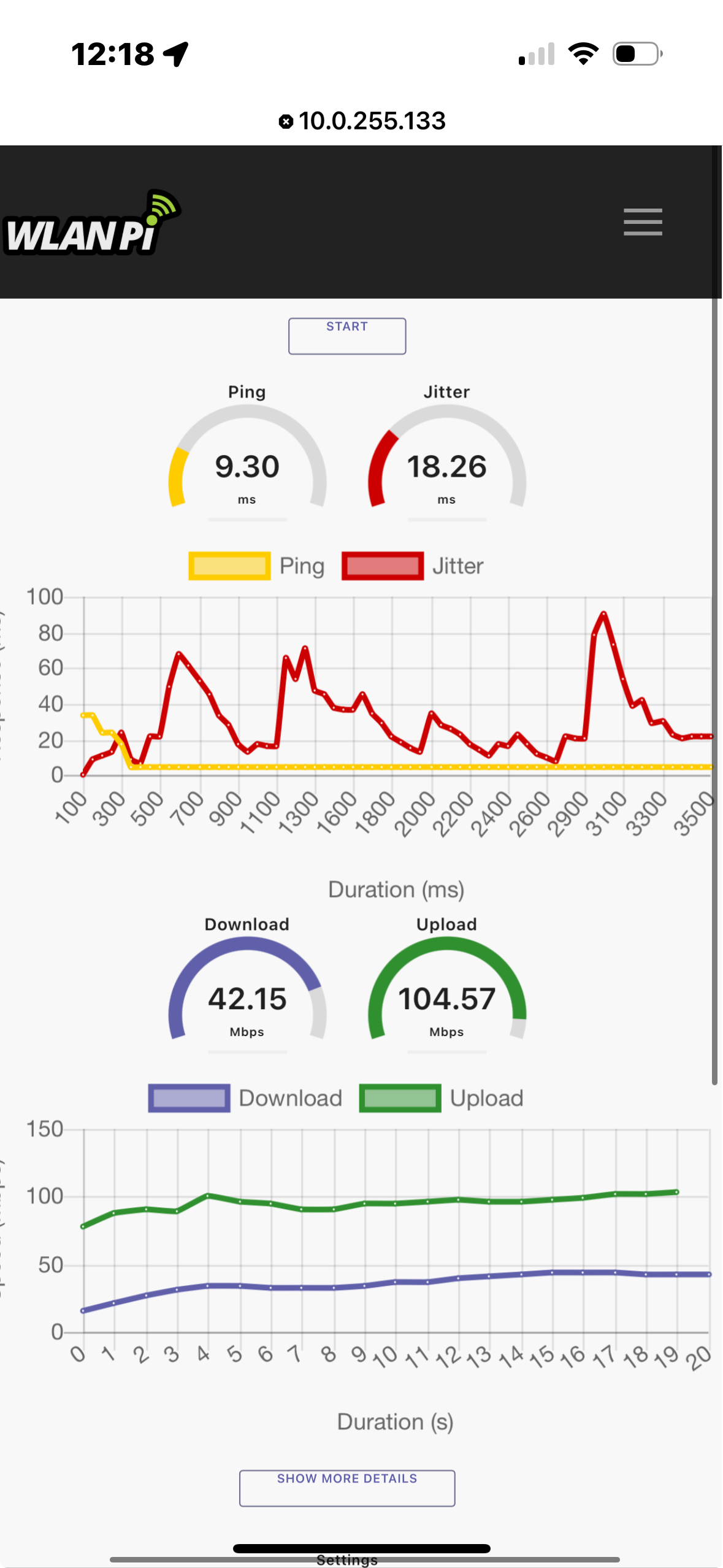
Librespeed was triggered on all clients within 10 seconds of starting the test on the first one, which would account for the deviation at the beginning of each test whilst negotiating channel access, and from the results it would appear that the channel is being shared relatively evenly.
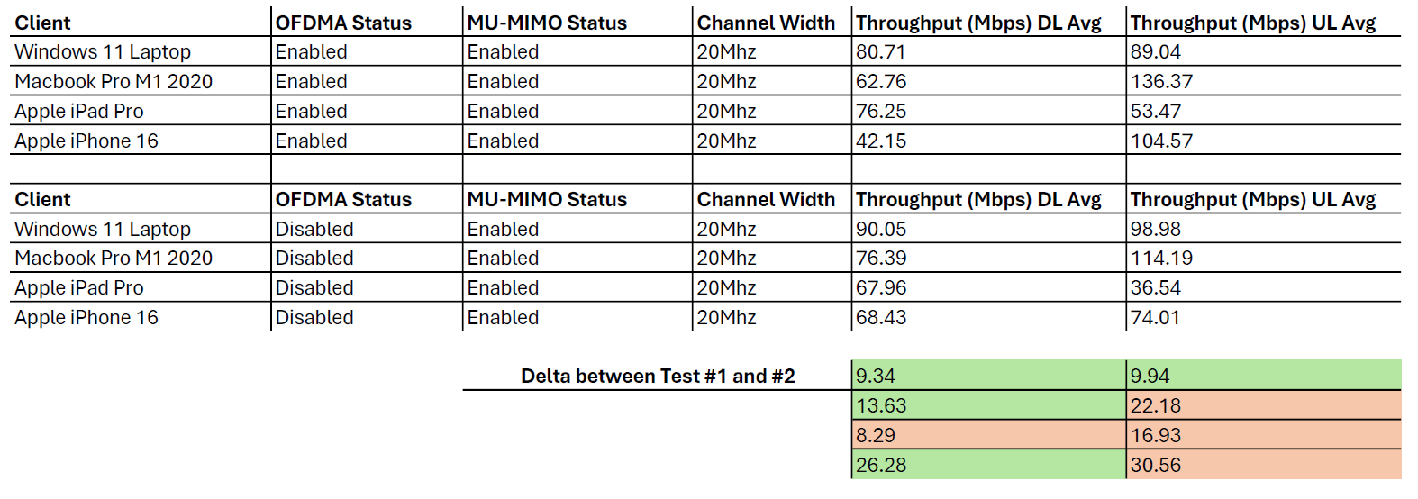
Tests were repeated with OFDMA enabled and disabled, MU-MIMO was left enabled in both circumstances.
OFDMA and MU-MIMO Enabled

OFDMA Disabled and MU-MIMO Enabled
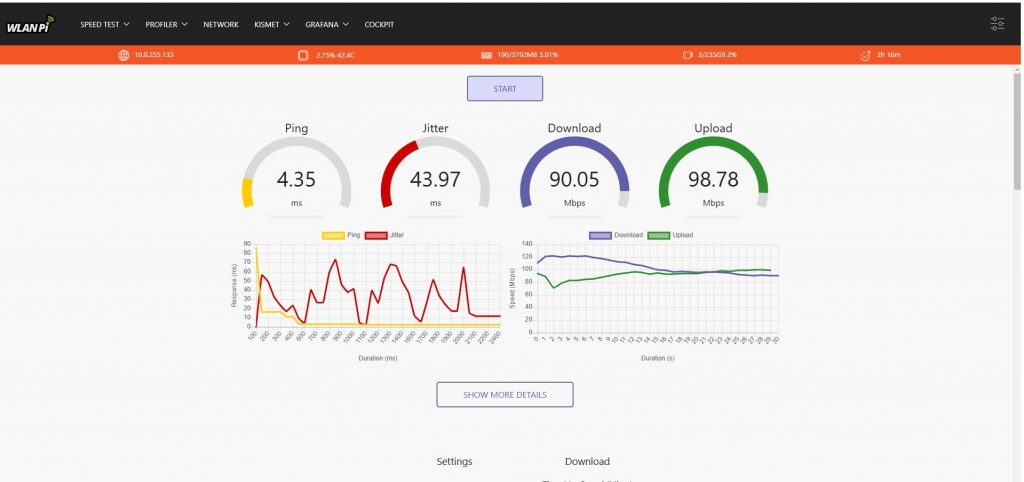
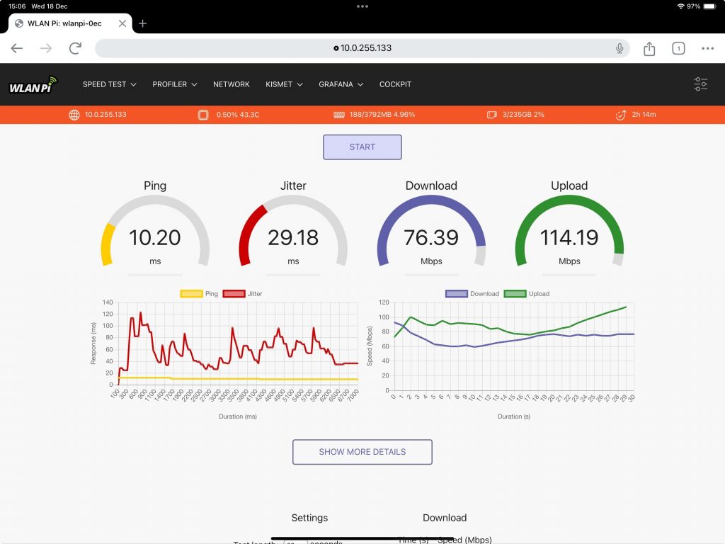
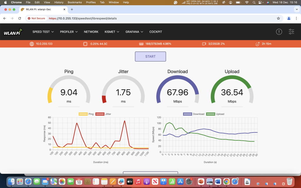
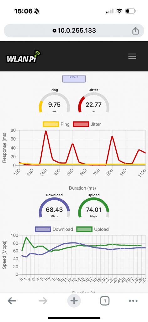
Throughput Test Results Summary
Summary of the results for both tests, with OFDMA disabled and enabled. Not much in it, and 3 out of the 4 STAs had higher throughput when OFDMA was disabled.
This was by no means an exhaustive test and was not repeated multiple times to generate an average of each throughput value.
To try and see if OFDMA was being used for multi-user transmissions, I tried to emulate a presentation at WLPC 2024 by Peter Mackenzie, named “Diessecting OFDMA” in which he used spectrum analysis to demonstrate DL and UL OFDMA operation through observation of the spectral mask. This is a brilliant visual representation of OFDMA working on a live network but with some noticeable observations in terms of if/when it is triggered and in uplink or downlink.
From the start of the video below, until 35 seconds, all transmissions are downlink (DS/AP > STA) from 35 seconds onwards, all transmissions are downlinked (STA > DS/AP)
There is a noticeable change in the spectral mask when observing DL and UL, although i am unsure if this is indicative of OFDMA, I think it may be more pronounced if using 40 or 80Mhz wide channels, a test which I will repeat at a later date.
That being said, with OFDMA disabled, there really didn’t seem to be a huge impact in terms of capacity on the 20Mhz channel, but overall was a net gain with only MU-MIMO enabled.
DL SU-MIMO HE – Channel Sounding Operation
When conducting the test, with MU-MIMO enabled, it was observed that regular sounding of the channel was being used.
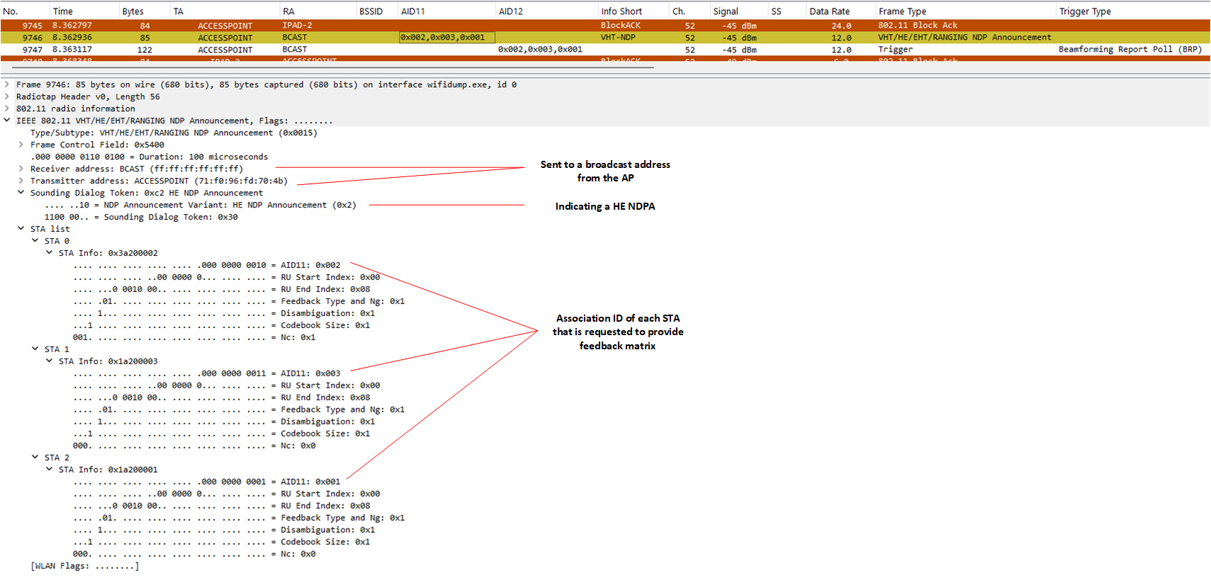
These frame exchanges differ from an MU-MIMO transmission in the fact that the frames have a unicast receiver address (RA) as opposed to a broadcast address, when NDPA frames are sent as broadcast, the receiving STAs are listed in the STA Information Fields Element.
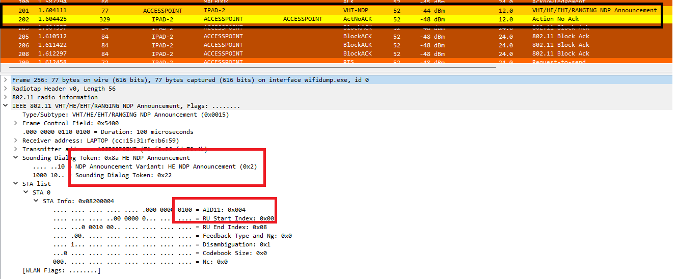
What we see in this capture is this exchange between the AP and a single STA.
- AP → STA(s): HE-NDP Announcement Frame
- AP → STA(s): HE-NDP Frame – Not visible
- STA(s) → AP: HE Compressed Beamforming Report
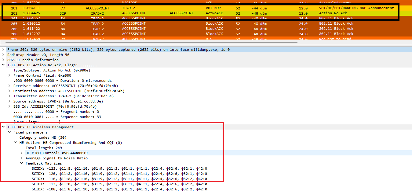
The frames below indicate that the AP was routinely requesting a feedback matrix from each associated STA based on unique AID.
DL/UL MU-MIMO HE Channel Sounding Operation
After a period of trial and error, I was finally able to trigger MU operation with 3 associated STAs. The only downside as mentioned earlier however was that i was not able to see the feedback matrix transmitted using UL MU-MIMO as I cannot capture the OFDMA transmission in this configuration.
Let’s start with what I could see.
- As expected, the first frame is an NDPA requesting CSI from 3 STAs.
2. Following the NDPA is the NDP PHY frame that cannot be captured.

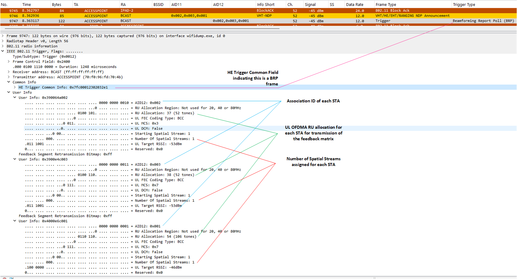
3. The next frame is the HE Trigger-based Beamforming Report Poll to request the feedback matrix from each STA listed.
4. Following this exchange, it is assumed that a UL-OFMDA transmission occurred and the compressed beamforming report from each STA was sent to the AP simultaneously.
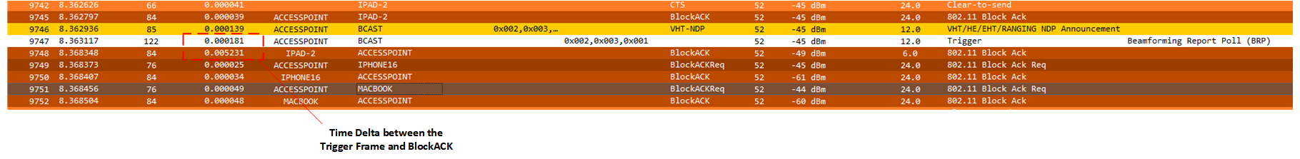
I am further comforted by the fact that the delta between the Trigger Frame and Block Ack is quite large which leads me to believe another frame exchange has occurred. (Thank you Peter Mackenzie’s CWAP course!)
What I was also expecting to proceed following this was another trigger frame – MU-BAR, which also relies on UL-OFDMA, instead we observe the exchange of multiple Block Ack Request and Block Ack frames for each STA within what I consider an MU-MIMO transmission based on my understanding of the standard.
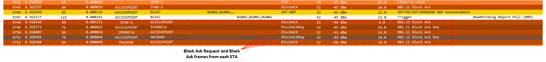
4. Once the MU-MIMO transmission has occurred, the AP then continues to poll STAs using SU-MIMO, triggering MU-MIMO seems to be opportunistic as the data transmission was still ongoing.


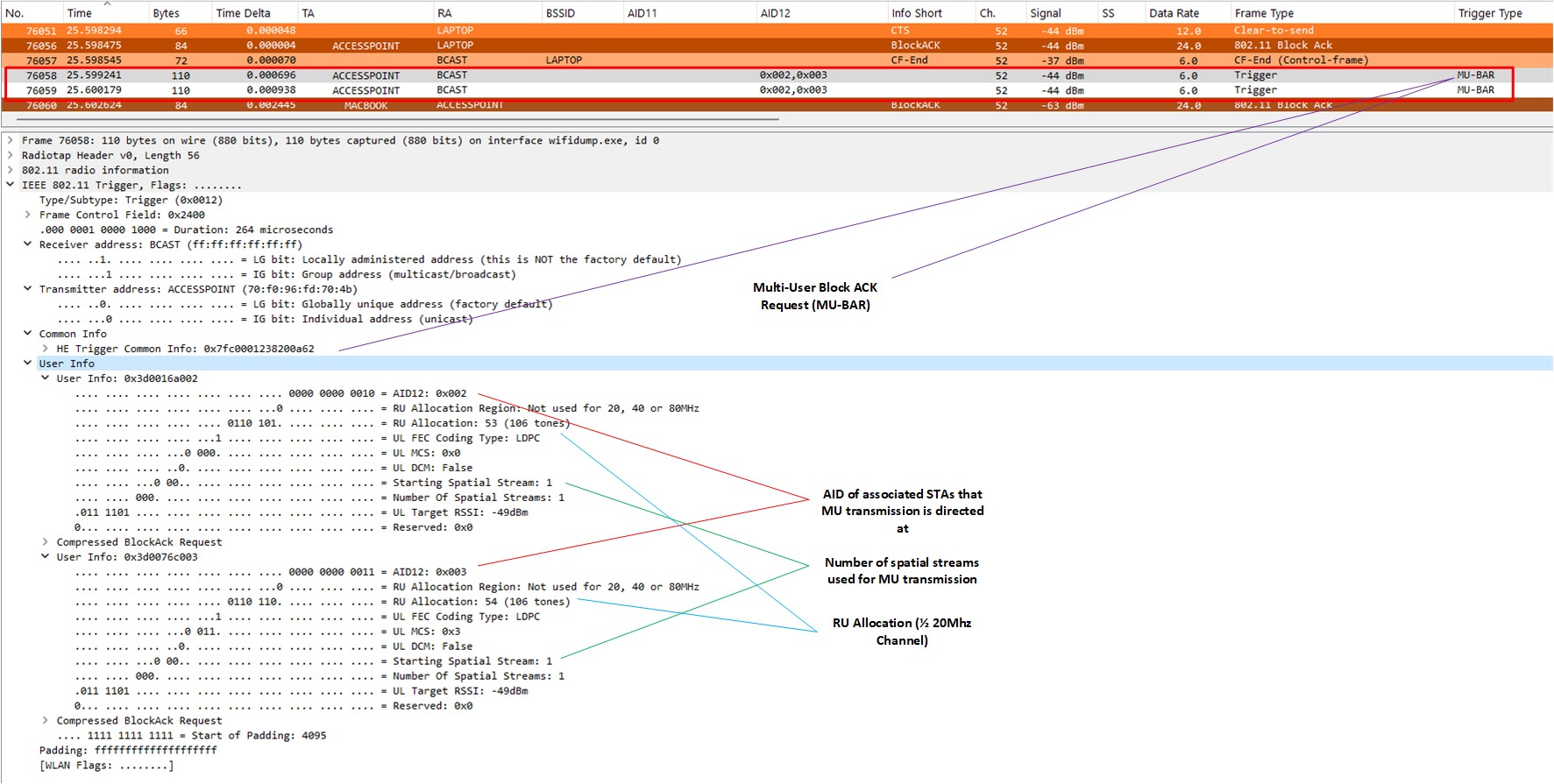
5. After a while, I was eventually able to capture MU-BAR frames, which indicates an MU transmission occurred, but not directly proceeding a sounding exchange. This requires further investigation as I was unable to get this to happen in sequence following the compressed beamforming report!
NB: A Multiuser Block-ACK Request (MU BAR) solicits BA or ACK frames from STAs to be multiplexed in an uplink MU transmissions)
Channel Sounding – Observations
Frame Sizes
One of my main concerns about MU-MIMO operation is the size of the frames exchange between the AP and STA to maintain CSI, even if OFDMA is used, this is still an overhead on the medium that should be considered, especially when trying to recover as much airtime as possible within a HD or VHD environment.
Whilst we can’t observe the MU compressed beamforming reports, we can see the SU transmissions, as will be explained further on, the associated frame sizes for MU could be even larger than observed.
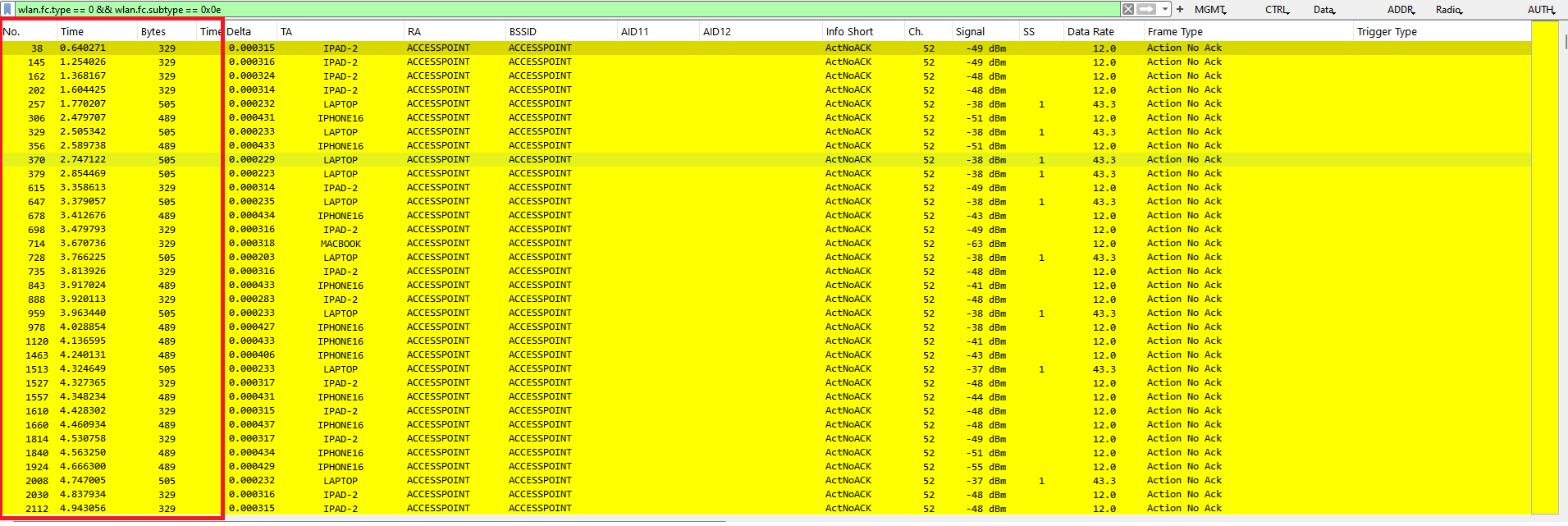
In this test, the size of the HE Compressed Beamforming Matrix, sent as an Action Frame varied quite considerably, below showing all the clients that were used in the test.
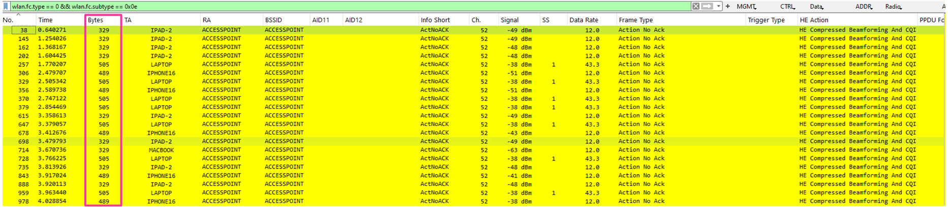
As you can see the frame size is between 329 bytes and 505 bytes, which is comparable to management frames (100 to 300 bytes) such as beacons, but much larger than a typical control frame (20 to 50 bytes)
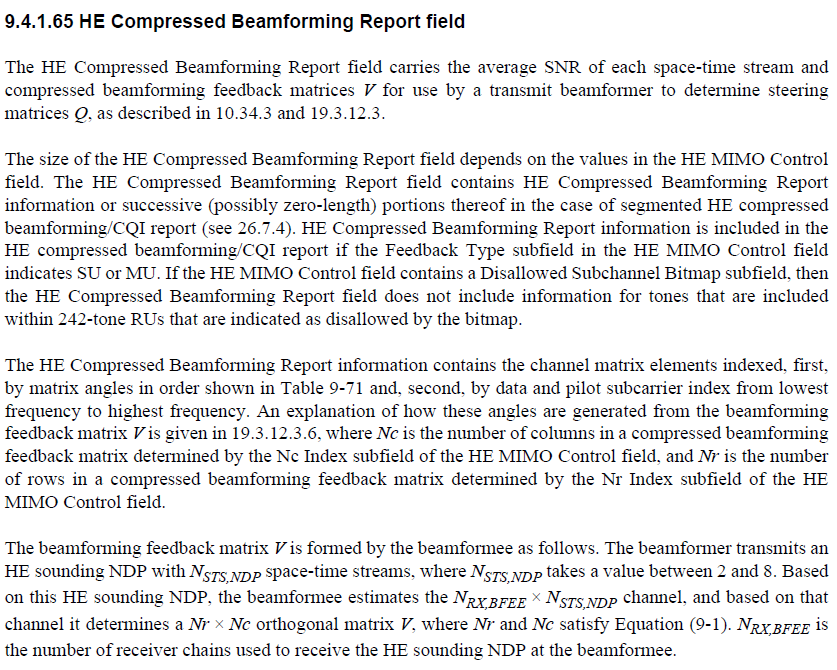
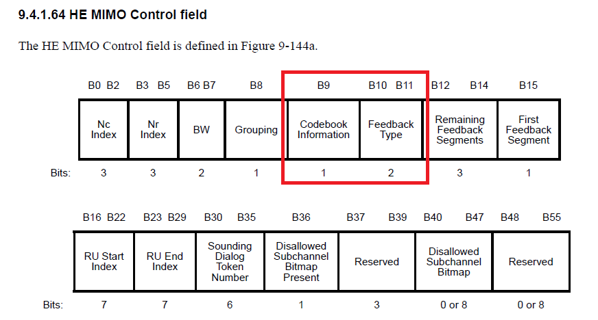
To explain this difference, we need to have a look at the IEEE 802.11ax 2021 standard, specifically, the following section detailing the HE Compressed Beamforming Report field.
I would recommend reading this to make further sense of it, but have extracted the key points, and for the record, there is some quite complicated maths behind how the AP calculates how to beamform to a single or group of STAs.
Factors that impact the size of the HE Compressed Beamforming frame
- Feedback Type (SU or MU):
- The Feedback Type indicates whether the report is for Single-User (SU) or Multi-User (MU) beamforming.
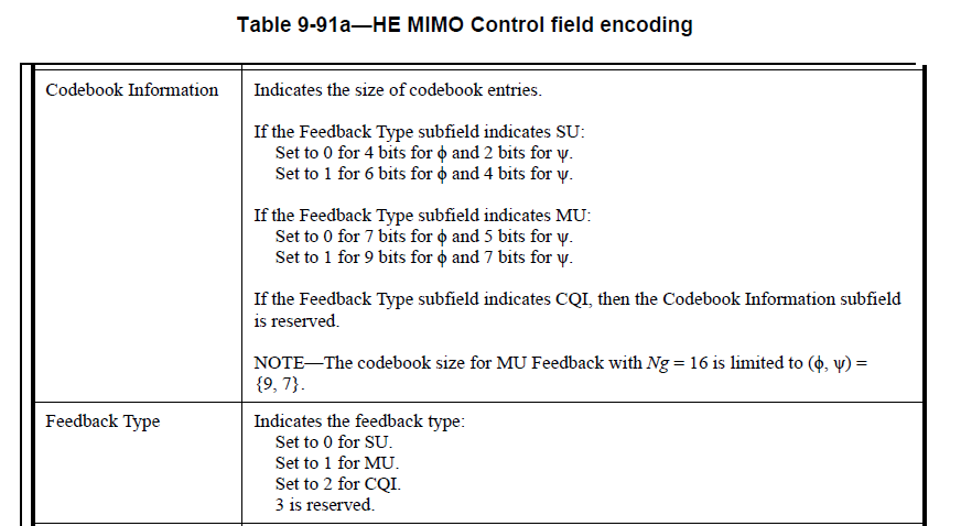
- Codebook Information:
- Indicates the size of codebook entries based on whether the feedback type subfield indicates SU or MU.
- Bandwidth:
- Wider channels have more subcarriers, so the feedback matrix must be larger to accommodate them.
- Number of Spatial Streams:
- Each spatial stream requires its own feedback data, and more angles to computate.
In this capture, these are SU-MIMO frames and not MU-MIMO transmitted as UL OFDMA, as such the feedback type is set to 0. These are set in the HE MIMO Control field.
The compressed beamforming matrix contains values called angles (phase information) that describe the relationship between the signals received at different antennas.
The angles describe how the signal behaves in the wireless channel between:
- Each transmit antenna at the AP, and
- Each receive antenna at the STA
Angles are used because they describe how signals arriving from multiple antennas interfere or combine in space. By adjusting the phase of signals using these angles, the AP can “steer” its signal to achieve the best performance.
The formula for calculating this is documented in the 80211-2020 standard in section 19.3.12.3.6 and I won’t pretend to understand the maths!
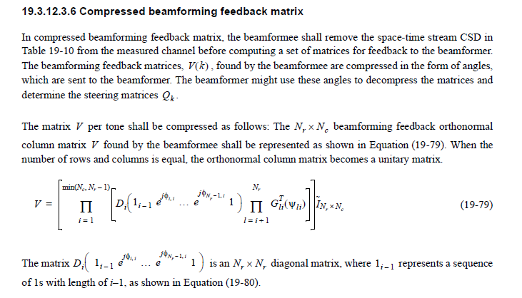
These angles are predefined in a codebook, If the codebook information bit is set to 0, the number of bits to quantize an angle in SU-MIMO is 4 or 2, if the value is set to 1, the number of bits to quantize an angle in SU-MIMO is 6 or 4, while they are 7 or 5, 9 or 7 in MU-MIMO implying that the compressed V-matrix in MU-MIMO has larger overhead compared to SU-MIMO.
Hence why there is a discrepancy between the sizes of the HE Compressed Beamforming frames between different types of STAs, as it is determined by the number of transmit and receive antennas and spatial streams used as part of the SU or MU transmission.
Frequency
The frequency at which an AP initiates a sounding exchange using an NDPA frame, to gather CSI is dependant on several factors.
- AP Scheduling Algorithm
- Network Load
- Channel Conditions
- Client Density
To try and establish whether this differed between a low density vs a high-density network, Ii compared the capture taken in a very low-density environment, with 4 stations, to a large public venue with over 5,000 active STAs.
This is by no means an exhaustive test but hopefully provides an indicator in terms of how network load and channel conditions impact the frequency an AP will attempt to sound the channel.
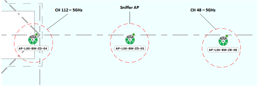
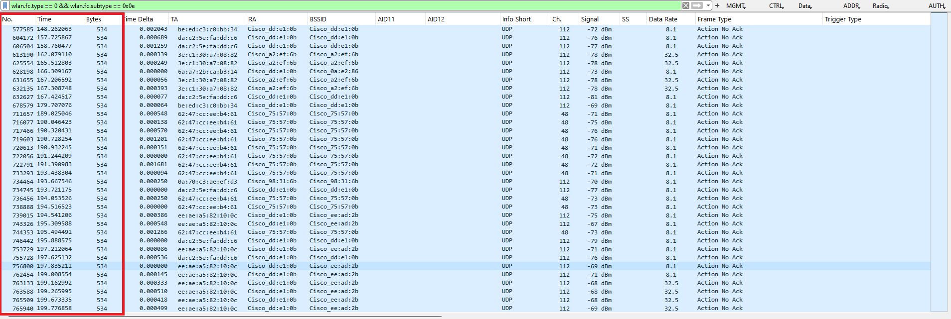
For the packet capture within the large public venue, i am using a Cisco 9130AXI AP w/ dual 5GHz radios and 9104 stadium antenna, capturing on 5GHz, Channels 112 and 48, set up in sniffer mode.
The antennas associated with these APs have a very tight beamwidth but high receive sensitivity, but was still hoping to capture frames from the nearest APs.
The AP that was put into sniffer mode was directly adjacent to other APs operating on these channels.
To measure this I am only looking at SU HE Compressed Beamforming Reports and use the Wireshark I/O graph to plot the number of frames per second.
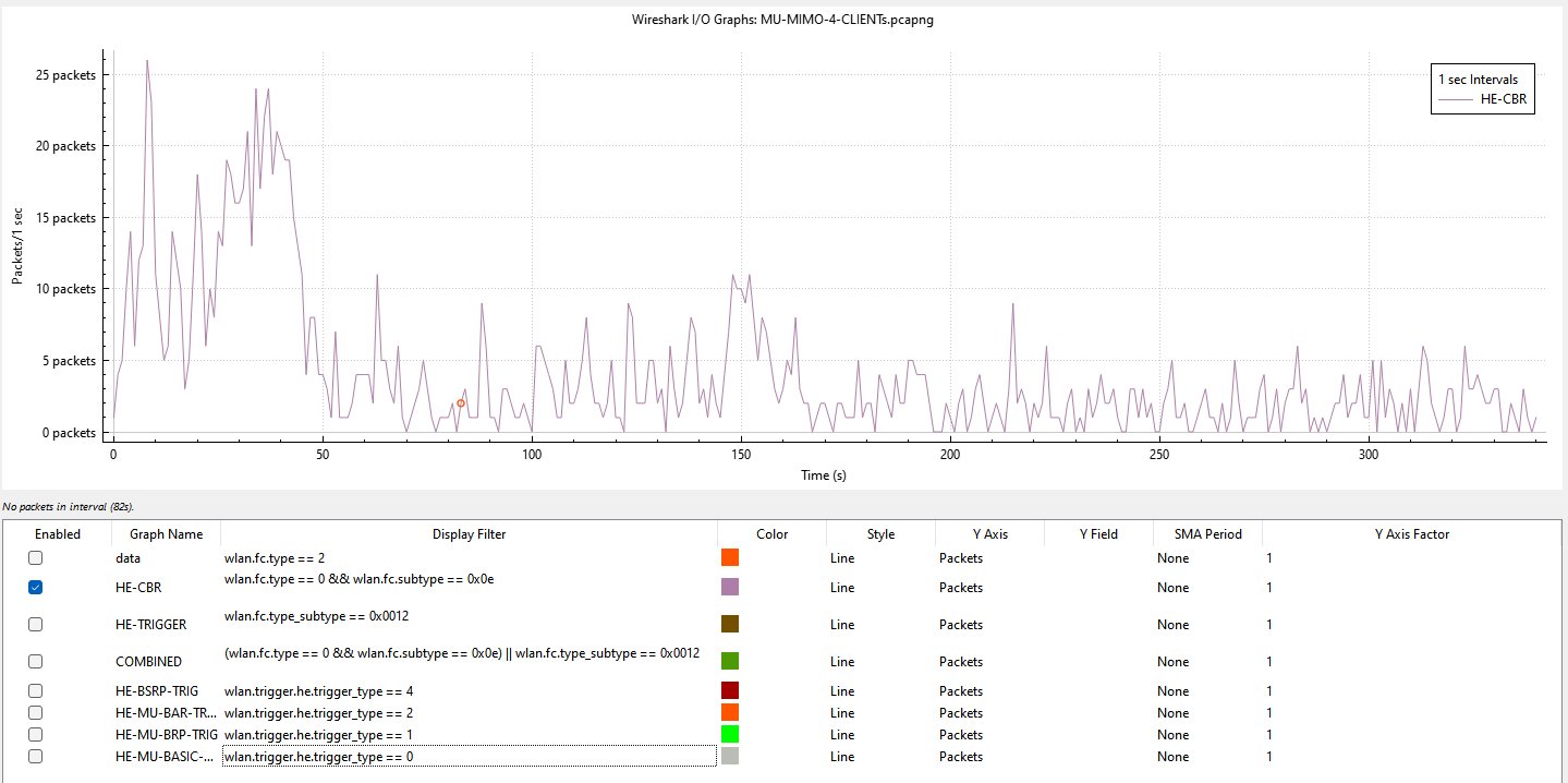
SU-MIMO HE-CBR Frame Count
Low Density – 4 STAs – 176304 Frame Count – 1384 SU HE-CBR (0.8%)
High Density – ~60 STAs per Radio – 1382907 Frame Count – 887 SU HE-CBR (0.1%)
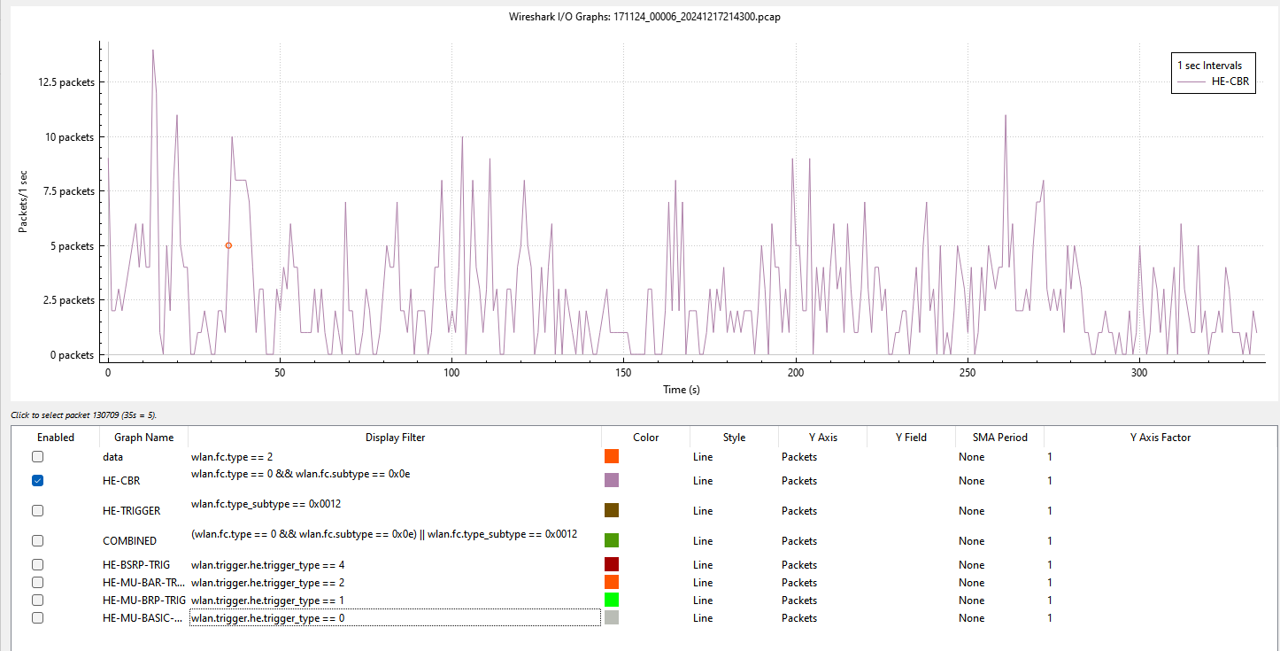
Ok, so we can see that SU MIMO sounding is happening, at regular intervals and seems to be impacted by channel load, or at least affected by the number of associated STAs per radio.
If we go one step further and assume that MU-MIMO is also occurring, we can filter this further and also now include the MU Trigger frames that are involved in OFDMA operations.
MU-MIMO HE-Trigger Frame Count
Low Density – 4 STAs – 176304 Frame Count – 7057 HE-CBR + HE-TRIGGER (4%)

- Looking at the percentage of MU Trigger frames would lead me to believe that MU-MIMO sounding is occurring a lot more often than SU-MIMO, but this could be normal OFDMA operation. I think what is key is the MU-BRP frames that proceed an MU Compressed Beamforming Report sent using UL-OFDMA.
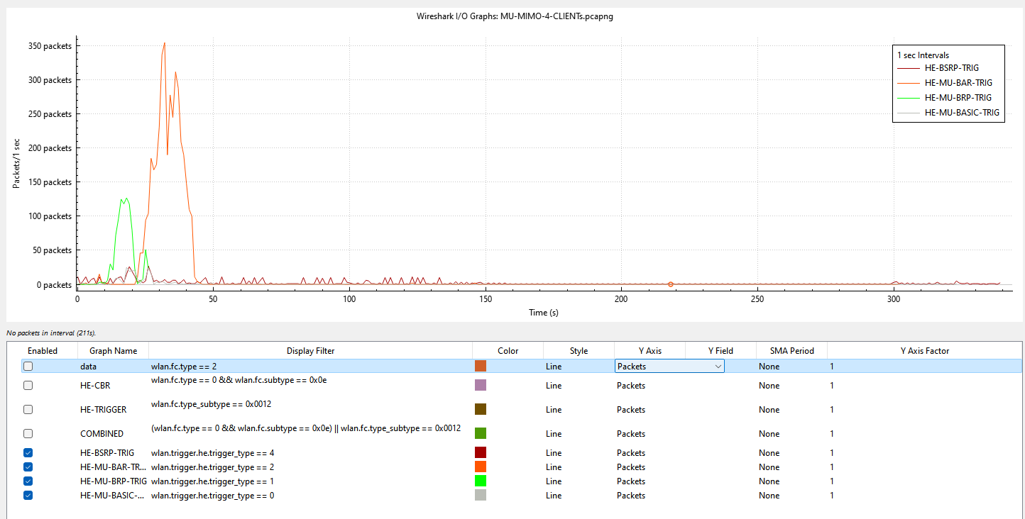
- 0.5% of the frames captured were MU Trigger Beamforming Report Poll Trigger Frames.
- 0.4% of the frames captured were MU Trigger Buffer Status Report Trigger Frames.
- 2.2% of the frames captured were MU Block Ack Request Trigger Frames.
- 0.1% of the frames captured were MU Basic Trigger Frames.
High Density – ~60 STAs per Radio – 1382907 Frame Count -17817 HE-CBR + HE-TRIGGER (1.3%)
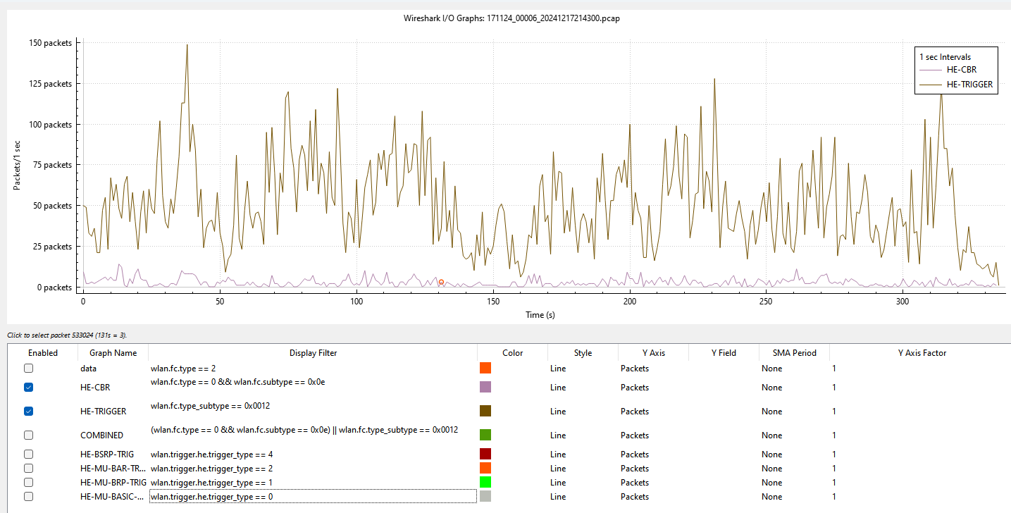
Looking at the percentage of MU Trigger frames would lead me to believe that MU-MIMO sounding is occurring a lot more often than SU-MIMO, but this could be normal OFDMA operation. However, if we split this into individual trigger frames, the number of HE-BRP captured is almost immeasurable, with only 50 captured out of 1382907 total.
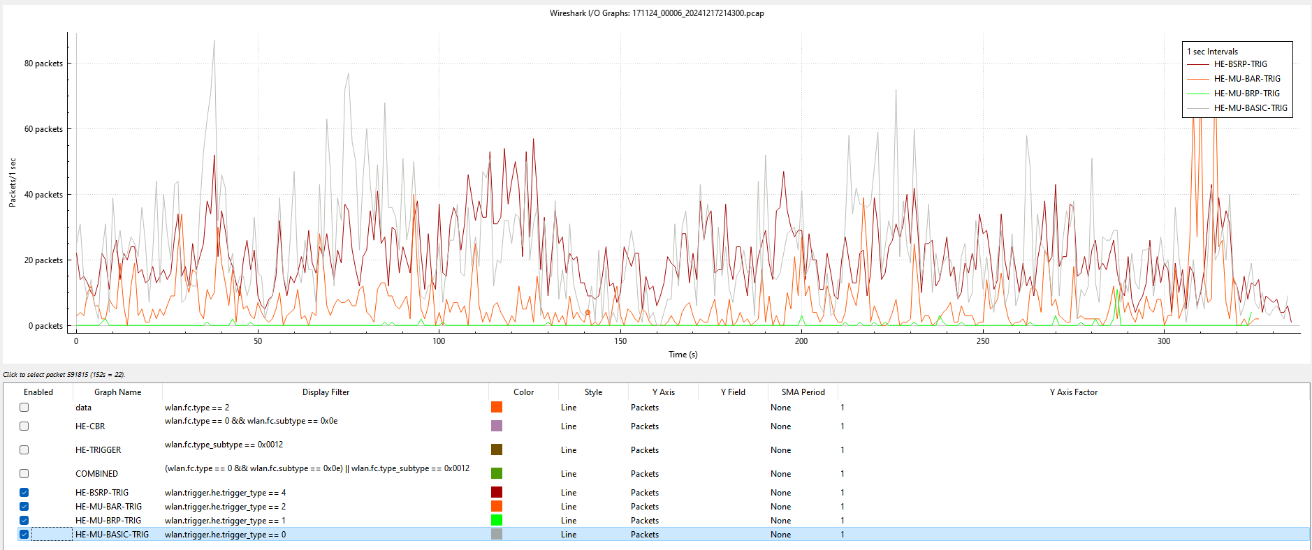
- 0.0% of the frames captured were MU Trigger Beamforming Report Poll Trigger Frames.
- 0.5% of the frames captured were MU Trigger Buffer Status Report Trigger Frames.
- 0.2% of the frames captured were MU Block Ack Request Trigger Frames.
- 0.5% of the frames captured were MU Basic Trigger Frames.
Channel Sounding Frequency – Conclusion
I definitely was not expecting that, although let’s consider what might be happening here.
In the first test, channel conditions are very stable, there is no contention as the AP is operating on a clean channel, all STAs are stationary, within close proximity to the AP and such channel state information (CSI) should remain consistent and stable, however, the AP scheduling algorithm seems quite content to add additional overhead in a low contention environment.
On the second test, channel conditions are fluctuating, the noise floor is raised due to a large number of people and transmitters in the venue, the load on the wireless system is very high, STAs are a much longer distance away from the AP, mobility is likely low, as during an event people movement is minimal, especially within seated areas and even within floor standing.
In this instance though it would seem that the AP scheduling algorithm is prioritising airtime efficiency as opposed to trying to maintain CSI.
Why might this happen?
- Channel sounding consumes airtime because it involves sending NDPA, NDP, and Compressed Beamforming Reports (Matrix V) which defers other transmissions.
- There is a high channel load and frequent sounding would reduce overall capacity.
- The AP appears to prioritise data traffic and reduces the frequency of sounding to balance performance and airtime usage.
- The average packet size for data transmission is low which does not benefit from MU-MIMO.
- STAs are too densely populated and spatial separation is not possible to achieve adequate channel sounding.
For the record, I don’t believe that these results are due to a low number of 802.11ax STAs, as data pulled from the wireless controller shows that >90% of STAs within the venue are 802.11ax capable.
Channel Sounding – Takeaways
When comparing MU-MIMO operation in both 802.11ac and 802.11ax, it would be reasonable to believe that the associated sounding overhead using the method described for 802.11ac would grow exponentially as the number of STAs also increased, due to the time period required between the NDP and receipt of all compressed beamforming reports, and that through the use of multiplexing (UL) using the trigger based method in 802.11ax it would improve performance, but the use of OFDMA is never guaranteed.
This process also assumes that channel conditions and medium contention are favourable, in a highly congested environment, the time between transmit opportunities (TxOp) could vary greatly, and its also important to note the frequency at which channel sounding needs to occur to maintain the CSI.
Some of the problems I believe that are faced with sounding are as follows:
- Calculation of CSI adds significant computational complexity at the AP.
- The sounding period is variable and has to occur very often (25-50ms) to maintain CSI from STAs, which incurs overhead, impacts spatial efficiency and adds latency, especially in complex physical environments with dense client groupings.
- The frame size of HE Compressed Beamforming report (Matrix V) is very large and sent often by STAs to calculate CSI, adding further overhead and reducing airtime efficiency.
- STAs that are not specified in the NDP defer channel access until the channel measurement is complete.
- Complexity is required to group suitable clients into a single MU-MIMO group.
- MU-MIMO requires the grouping of STAs with similar attributes and spaced evenly around the AP, which is difficult to promote in complex or dense environments.
Conclusion
Based on the analysis conducted thus far, it has been shown that MU-MIMO does operate as expected when channel conditions are favourable and can allow for increased capacity within a BSS, even when sounding overhead is high.
Based on the understanding of MU-MIMO operation, the required frame exchanges to calculate CSI and the associated overhead attributed to the sounding process, it does not seem to promote its use within high-density or more complex physical environments, based on evidence collected to date, it would also seem that the way scheduling algorithms within the APs on the test are configured, channel access and airtime efficiency are favoured over MU-MIMO operation, which, even if enabled would result in STAs preferring SU-MIMO operations and likely favour other multi-user technologies such as OFDMA for channel access, using Resource Units (RUs), allowing multiple devices to transmit or receive data simultaneously within the same channel.
Would I enable MU-MIMO in an HD environment? No, but not for the reasons I first believed to be true, quite the opposite, even when enabled, it appears to be used very little, if at all, especially under high channel load.
Any thoughts or opinions on this article are welcome, this is a very complex topic, and have tried very hard to be factual.
Sources:
Revisiting Multi-User Downlink in IEEE 802.11ax: A Designers Guide to MU-MIMO
Performance evaluation of OFDMA and MU-MIMO in 802.11ax networks
Implementation and Evaluation of IEEE 802.11ax Channel Sounding Frame Exchange in ns-3
A Novel Low-Overhead Channel Sounding Protocol for Downlink Multi-User MIMO in IEEE 802.11ax WLAN